Purpose of a Transmission
Before we get into the ins and outs of how an automatic transmission works, let’s do a quick review of why vehicles need a transmission of any kind in the first place.
As discussed in our primer on how a car engine works, the engine of your vehicle creates rotational power. To move the car, we need to transfer that rotational power to the wheels. That’s what the car’s drive train which the transmission is a part of does.
But here’s the problem: an engine can only spin within a certain speed in order to operate efficiently. If it spins too low, you wouldn’t be able to get the car moving from a standstill; if it spins too fast, the engine can self-destruct.
What we need is some way to multiply the power produced by the engine when it’s needed (starting from a standstill, going up a hill, etc.), but also decrease the amount of power sent from the engine when it isn’t needed (going downhill, going really fast, slamming on the brakes).
Enter the transmission.
The transmission ensures that your engine spins at an optimal rate (neither too slow nor too fast) while simultaneously providing your wheels with the right amount of power they need to move and stop the car, no matter the situation you find yourself in. It sits between the engine and the rest of the drivetrain and sort of acts like a power switchboard for the car.
We previously went into detail on how manual transmissions accomplish this through gear ratios. By connecting different sized gears with one another, you can increase the amount of power that is delivered to the rest of the car without changing the speed of the engine’s rotational power all that much. If you don’t yet grasp the idea of gear ratios, I recommend you watch the video we included last time before you move on; nothing else will make sense unless you understand this concept.
With a manual transmission, you control which gears are engaged by pressing the clutch and shifting the gears into place.
On an automatic transmission, brilliant engineering determines which gear is engaged without you having to do a dang thing except to press the gas or the brake pedals. It’s automotive magic.
Parts of an Automatic Transmission
So by now, you should have a basic understanding of a transmission’s purpose: it ensures that your engine spins at an optimal rate (neither too slow nor too fast), while simultaneously providing your wheels with the right amount of power to move and stop the car, no matter the situation.
Let’s take a look at the parts that allow this to happen in the case of the automatic transmission:
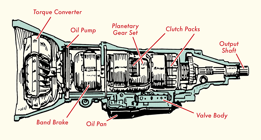
Transmission Casing
A transmission casing houses all the parts of the transmission. It sort of looks like a bell, so you’ll often hear it referred to as a “bell casing.” The transmission casing is typically made of aluminum. Besides protecting all the moving gears of the transmission, the bell casing on modern cars has various sensors that track input rotational speed from the engine and output rotational speed to the rest of the car.
Torque Converter
Ever wonder why you can turn on your car’s engine, but not have the thing move forward? Well, that’s because power flow from the engine to the transmission is disconnected. This disconnection allows the engine to continue running even though the rest of the car’s drivetrain isn’t getting any power. On a manual transmission, you disconnect power from the engine to the drivetrain by pressing in the clutch.
But how do you disconnect power from the engine to the rest of the drivetrain on an automatic transmission that doesn’t have a clutch?
With a torque converter, of course.
This is where the black magic of automatic transmissions begins (we haven’t even gotten to planetary gears yet).
The torque converter sits between the engine and the transmission. It’s a donut looking thing that sits inside the big opening of the transmission’s bell case. It has two primary functions in terms of transmitting torque:
- Transfers power from the engine to the transmission input shaft
- Multiplies engine torque output
It performs these two functions thanks to hydraulic power provided by the transmission fluid inside your transmission.
To understand how this works, we need to know how the different parts of a torque converter work.
Parts of a Torque Converter
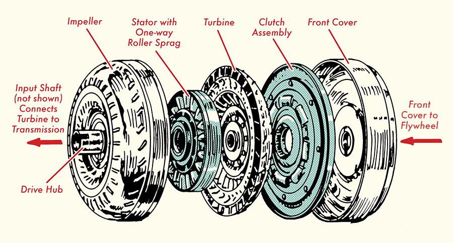
There are four main parts of a torque converter in most modern vehicles: 1) the pump, 2) the stator, 3) the turbine, and 4) the torque converter clutch.
1. Pump (aka impeller). The pump looks like a fan. It has a bunch of blades radiating from its center. The pump is mounted directly to the torque converter housing which in turn is bolted directly to the engine’s flywheel. Consequently, the pump spins at the same speed as the engine’s crankshaft. (You’ll need to remember that when we walk through how the torque converter works.) The pump “pumps” transmission fluid outwards from the center towards the . . .
2. Turbine. The turbine sits inside the converter housing. Like the pump, it looks like a fan. The turbine connects directly to the input shaft of the transmission. It’s not connected to the pump so it can move at a different speed than the pump. This is an important point. This is what allows the engine to turn at a different speed than the rest of the drivetrain.
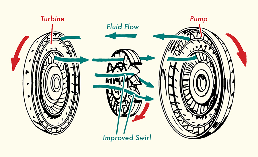
The turbine can spin thanks to the transmission fluid that gets sent from the pump. The turbine’s blades are designed in a way so that the fluid it receives is moved towards the center of the turbine and back towards the pump.
3. Stator (aka Reactor). The stator sits between the pump and turbine. It looks like a fan blade or airplane propeller (do you see a pattern here?). The stator does two things: 1) sends transmission fluid from the turbine back to the pump more efficiently, and 2) multiplies torque coming from the engine to help get the car moving, but then sends less torque once the car is going at a good clip.
It accomplishes this thanks to some clever engineering. First, the blades on the reactor are designed in a way so that when the transmission fluid leaving the turbine hits the stator’s blades, the fluid is diverted in the same direction as the pump’s rotation.
Second, the stator is connected to a fixed shaft on the transmission via a one-way clutch. This means that the stator can only move in one direction. This ensures that fluid from the turbine is directed in one direction. The stator will only start spinning when the fluid speed from the turbine reaches a certain level.
These two design elements of the stator make the work of the pump easier and generate more fluid pressure. This, in turn, creates an amplified torque at the turbine and because the turbine is connected to the transmission, more torque can be sent to the transmission and the rest of the car. Whew.
4. Torque converter clutch. Thanks to how fluid dynamics work, power is lost as the transmission fluid goes from the pump to the turbine. This results in the turbine spinning at a slightly slower speed than the pump. This isn’t a problem when the car is getting going (in fact that speed difference is what allows the turbine to deliver more torque to the transmission), but once it’s cruising, that difference results in some energy inefficiencies.
To negate that energy loss, most modern torque convertors have a torque convertor clutch that’s connected to the turbine. When the car reaches a certain speed (usually 45-50 mph), the torque converter clutch engages and causes the turbine to spin at the same speed as the pump. A computer controls when the converter clutch is engaged.
So those are the parts of the torque converter.
Let’s bring it all together and take a look at what the action of the torque converter would look like as you go from a dead stop to a cruising speed:
You turn on the car, and it’s idling. The pump is spinning at the same speed as the engine and is sending transmission fluid towards the turbine, but because the engine isn’t spinning very fast at a dead stop, the turbine doesn’t spin that fast, so it can’t deliver torque to the transmission.
You step on the gas. This causes the engine to spin faster, which causes the torque converter pump to spin faster. Because the pump is spinning faster, transmission fluid is moving fast enough from the pump to start spinning the turbine faster. The turbine blades send the fluid to the stator. The stator isn’t spinning yet because transmission fluid speed isn’t high enough.
But because of the design of the stator’s blades, as the fluid passes through them, it diverts the fluid back to the pump in the same direction as the pump is spinning. This allows the pump to move the fluid back to the turbine at a higher speed and creates more fluid pressure. When the fluid heads back to the turbine, it does so with more torque, causing the turbine to deliver more torque to the transmission. The car starts moving forward.
Over and over this cycle continues as your car speeds up. When you reach cruising speed, the transmission fluid reaches a pressure that causes the reactor blades to finally spin. With the reactor spinning, torque is reduced. At this point, you don’t need much torque to move the car because the car is moving at a good clip. The torque converter clutch engages and causes the turbine to spin at the same speed as the pump and the engine.
Comments
Post a Comment